1. ERV/HRV Balancing Background and Overview
I decided to write this guide after reading through the Honeywell install manual for a ERV and HRV I installed and being very dissatisfied with the ventilator balancing instructions. I figured there must be others out there wanting some clarity on how to balance a ERV/HRV properly. Balancing a ventilation system is something normally left for the pros, but an extreme DIY’er can do it if they have a good understanding of the whole system. It is possible to balance your ERV or HRV without any special tools like a manometer or magnehelic differential pressure gauge if absolutely needed, which I will explain below, but still best to have some measurement devices. A word of caution, this is something you don’t want to mess up, proper balanced ventilation is absolutely essential in certain climates. In the north, where vapor barriers are used, if the house is under positive pressure you will be pushing moist air into the wall cavities in the winter where it can condensate. But regardless of the climate it is still important to have a balanced system. If you have any doubt get a pro in to do it. I will not dive too much into how to install a whole house ventilator as it is outside the scope of this article and something best left to a pro if you are unsure of how to do it.
2. Factors that Influence Balancing
In an ideal world with ventilation the goal is to have the total amount of fresh air entering the house match the total amount of air leaving the house. That is the goal but will not be able to be met at all times of operation in real world situations. Most installers balance their ERV / HRV installs to match the amount of air flowing into the ventilator to the amount of air exiting the ventilator, in other words both air streams have the same flow rate. This is a safe bet for most installs and a good way to go if you do not know how the homeowner operates the systems in the house on a day to day basis but does not guarantee the house will be pressure neutral. There are a lot of factors in a home that can influence the amount of air entering and leaving a home day to day that will throw off the balance, some will not be able accounted for no matter how you balance your ventilation system.
- The stack effect, warm air rising in a house pushing out the attic, exhaust pathways, cracks in the high locations in a house which will change with time of day and outdoor conditions
- If your ventilator is ducted into the existing home’s HVAC ductwork the HVAC blower blower speed determined by what mode the HVAC equipment is running in and how dirty the filters will affect the ventilators airflow
- Radon mitigation system
- Exhaust pathways such as bath fans, range hood fans, clothes dryer, central vacuum
- Natural gas appliances that pull air from the home for combustion instead of direct vent (intake air for combustion is taken from outside). In most cases these are the lower efficiency versions of water heaters and furnaces.
- Open windows or doors
If you understand all the factors involved you may want to balance a ventilator to have the total fresh air coming into the ventilator match the total amount of air exiting the house at a house’s average steady-state to keep the house pressure neutral. I call this micro-balancing as you are fine tuning the ventilator and not just measuring air in and out of the ventilator, I am not sure if micro-balancing is the official terminology for this.
3. Common Installation Configurations
3.1 Fully Dedicated (Independent) System
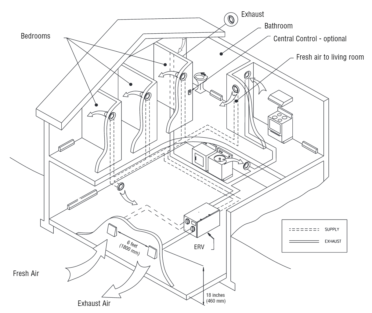
This system configuration has fully dedicated ductwork for ventilation, this is the best option if you are building a home from scratch or doing a major remodel. It is the most expensive and technically complex way to install a ventilation system but provides the most advantages over other methods. I would recommend adding filtration to the incoming air stream before the ERV to filter out pollen and other allergens from the outside air.
Advantages:
– Allows targeted removal of air from most common stale air locations and delivers fresh air to targeted spaces like bedrooms. Also rooms with higher humidity can be targeted as stale air exhaust.
– Does not connect to central HVAC system so this setup will not require HVAC blower motor to run to ventilate. If the furnace fan is not set to run constantly (which is recommended for air filtration) this configuration will reduce energy costs and in humid climates will help keep indoor humidity under control as the HVAC blower motor can shut off after the AC runs to allow condensation formed on the indoor cooling coil to drain. Otherwise air flowing over the indoor cooling coil in the HVAC equipment after the AC runs will pick up condensation moisture formed on the indoor cooling coil.
Disadvantages:
– Most expensive and the needs most extensive planning and engineering for duct calculations
3.2 Partially Dedicated System (Source Point Ventilation)

This system configuration uses dedicated ductwork to pull stale air from one or more locations in the home and dumps the fresh air from outside into the HVAC ductwork to be distributed around the house.
Advantages:
– Lower installation cost than dedicated system
– Allows targeted removal of air from most common stale air locations, also rooms with higher humidity can be targeted for stale air exhaust.
Disadvantages:
– Does not allow targeted supply of fresh air to specific rooms
– Needs more planning and labor cost then a simplified installation
– Requires HVAC equipment blower to run when ventilator is running
3.3 Simplified (Volume Ventilation)

This is the most cost effective system configuration, it requires the least amount of ductwork, labor and planning. It uses dedicated ductwork to pull stale air from one or more locations in the home and dumps the fresh air from outside into the HVAC ductwork to be distributed around the house.
Advantages:
– Lower installation cost than a dedicated system or a partially dedicated system
Disadvantages:
– Does not allow targeted removal of air from most common stale air locations and rooms with higher humidity
– Does not allow targeted supply of fresh air to specific rooms
– Requires HVAC equipment blower to run when ventilator is running
4. Recommended Tools
If you micro-balance based on home pressure relative to outdoor pressure which is described in the section 5 balancing procedure you do not have to measure the air streams on the ventilator but I prefer to measure the air streams even when microbalcing to get an idea how much “bias” I am putting on one of the air pathways to get the house to neutral pressure.
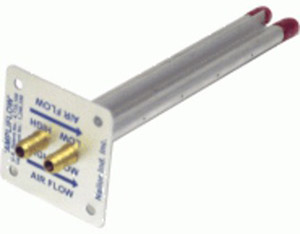
4.1 Probe to measure airflow
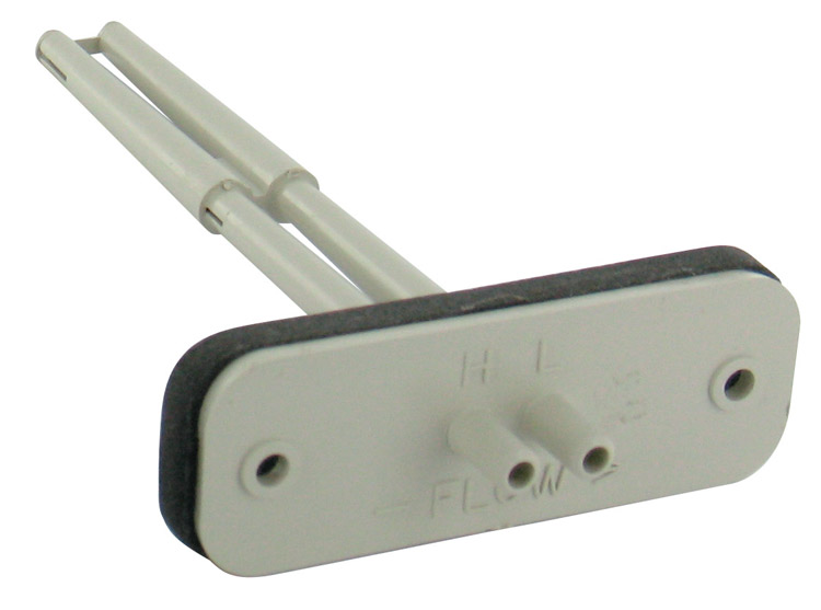
Below are probes to measure velocity pressure, which is the difference between the total pressure reading and the static pressure reading. These probes will have two ports, the high side (total pressure) port on the probe will connect to a hole or a set of holes that are facing into the airflow. The low side (static pressure) port will connect to a hole or set of holes on the probe that are in the same direction of the air stream or at 90 degrees to the air stream.
 Aprilaire Part Number 5158 Cost: ~$100 |
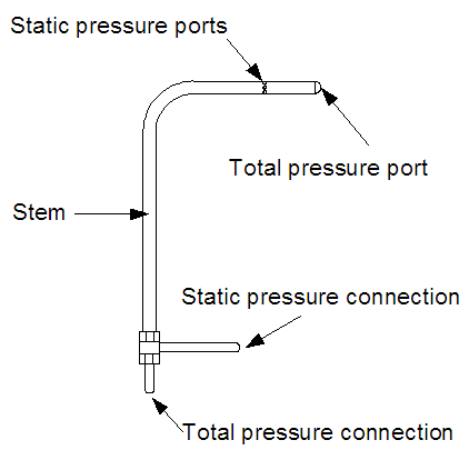 Image Source: Flow Kinetics |
 |
| Aprilaire Part Number 5158 Cost: ~$100 |
Velocity (differential) pressure pitot tube Cost: ~$90 |
Dwyer series PAFS-1000 averaging flow sensor PAFS-1002 – Averaging flow sensor, 3-5/32″ (8.02 cm) insertion length PAFS-1003 – Averaging flow sensor, 5-13/32″ (13.73 cm) insertion length Cost: ~$10 |
There are a couple types of probes you can put into the air stream to measure airflow. The Dwyer series PAFS is the least accurate but will be good enough in most cases. There is also what is called a flow collar but are very expensive and requires modifying the ductwork to put into the air stream, the above options are a better choice. The Aprilaire flow station is the best choice for accuracy in this application, if you can find sources to buy them below are some other options.
Other airflow station/grid options:
– Imperial Airflow Grid
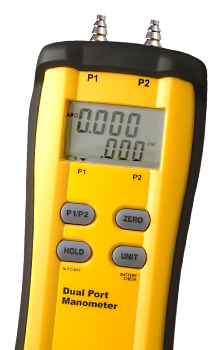
4.2 Differential Pressure Gauge
Dwyer series 2000 magnehelic differential pressure gauge
– Dwyer 2000-00AV, Range 0-0.25″WC & 0-2000 fpm – $88
– Dwyer 2000-00D, Range 0-0.25″WC & 0-62 Pa – $75
– Dwyer 2000-00D, Range 0-0.25″WC
I have used both and for balancing I prefer a analog magnehelic differential pressure gauge, it is lower cost and it is nice to see the needle of the gauge move as you probe around the air stream.
5. ERV/HRV Ventilator Balancing Procedure
The are two types of ERV/HRV ventilators on the market, single speed or selectable multi-speed blower and electronically controlled variable speed blower units. The ventilators with single speed or selectable multi-speed blowers require dampers installed in the ventilation ductwork to balance the system. The variable speed blower units allow individual speed adjustments of the intake and exhaust blower to dial in airflow. I prefer the variable speed units as they are more efficient.
5.1 Measuring airflow
Measuring airflow is not required for micro-balancing but I recommend it.
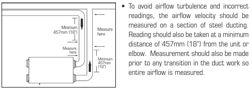
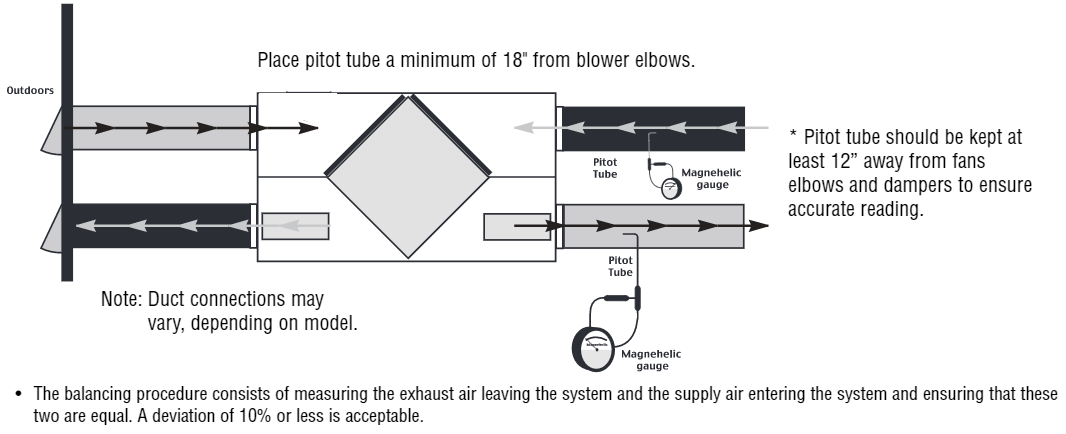
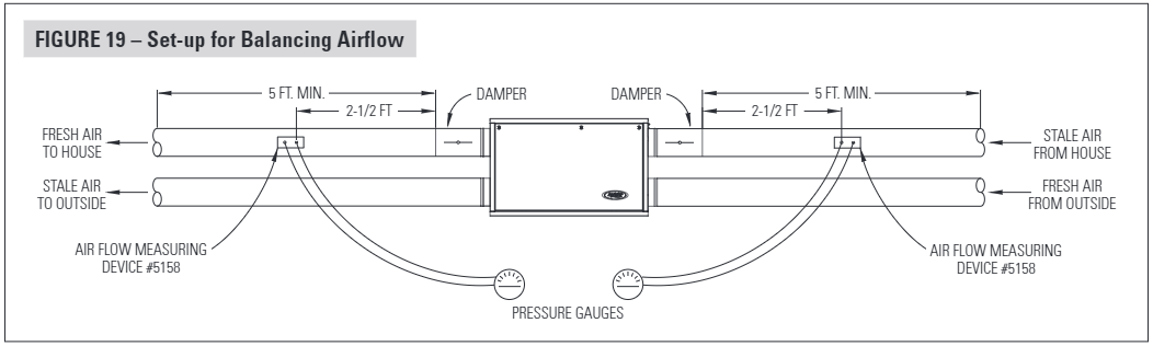
I reference a few diagrams from multiple installation manuals so you can see the various manufactures’ recommended measurement locations and recommended clearance distances for the most accurate measurement. I have modified a few slightly to add clarity.
Fantech SER Series Installation Manual
Broan 100H & 200H Installation Manual
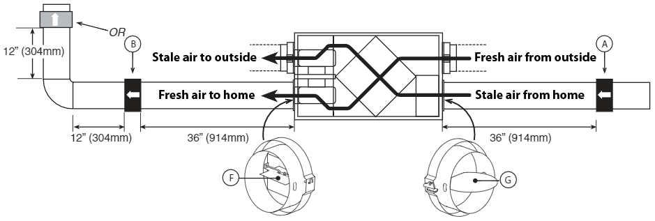
AprilAire 100 Energy Recovery Ventilator Installation Manual
Other Installation Manuals for Reference
5.2 Airflow Tables Found in Manufacture Product Data and Manuals
The manufacturer’s ERV/HRV installation manual or datasheet will include a table and/or graph showing the relationship of static pressure to airflow. It is important to note these tables and graphs are only valid when the blowers are on full speed, if you have a variable speed unit and you reduce the blower speed you can not use this data to determine the CFM or L/s through your ventilator. At the time of writing this article Honeywell’s manual is very bad about describing this, it says to use the external static pressure air flow table to balance the ventilator which does not work because once you lower the blower speed the data in the table is no longer accurate.
If you have a single speed ventilator with dampers you can use the manufacturer’s airflow data to determine the CFM flow rate with two static pressure probes. Static probes have one pressure port that is positioned to measure static pressure inside the duct. To measure the external static pressure used in the manufacturer’s air flow tables you need to place a static pressure probe on each side of the ventilator core in one air stream like the intake or exhaust. These probes must be placed BEFORE the air flow dampers i.e. between the blower and the damper. Some ventilators have ports built into the collars or on the door for this measurement. The pressure difference between these two measurements is the external static pressure.
5.3 Calculating Airflow (CFM or L/s)
At this time I am obmitting this section as the equations to calculate airflow from the velocity pressure readings can be found pretty easily on the internet. This is also not needed unless you want to dial in a specific airflow rate to hit a target ventilation standard like ASHRAE 62.1 & 62.2.
5.4 Balancing ERV/HRV using airflow
This procedure requires a manometer or magnehelic differential pressure gauge to measure differential pressure and a probe to go into the air stream outlined in section 4 of this article.
- Put the house into a “steady-state”, the most common conditions the home will see which is all windows closed, all exhaust fans off (don’t forget the clothes dryer), and turn the HVAC blower on if the ventilator is connected to the HVAC equipment or if the HVAC blower is normally left on.
- If using a magnehelic gauge place it on a level surface and zero out the dial.
- If the ventilator is a single-speed/multi-speed ventilator with dampers turn the ventilator on (set to high speed if multi-speed) and set both dampers to fully open. If using a variable speed blower ventilator unit, put the ventilator into balancing mode and set both blowers on full speed.
- Connect tubing from gauge to the measuring probe, be sure to connect the tubes to their appropriate high/low fittings. High will be the port facing the the air stream and low will be the static pressure side of the probe. When you put the probe into the air stream following the airflow arrow of the probe if the gauge drops below zero, reverse the tubing connections.
- Start by placing the probe into the exhaust air stream that is leaving the house prior to going through the ventilator core. The exhaust air flow is measured first, it typically has more restriction than the fresh air, especially in cases of fully ducted installations and exhaust ducted installation Try to pick a location outlined in the diagrams in section 5.1, it should be a straight run section of metal duct close to the ventilator but if possible a minimum of 18″ (preferable 36″) from the unit or elbow. Record the reading on the gauge.
- Place the measurement probe into the fresh air from home stream similar to the procedure outlined in step 5, record the reading.
- Typically the fresh air coming into the home will have a higher reading so adjust the damper on the fresh air side on units with a damper or adjust the fresh air blower motor speed on variable speed units until the reading matches the reading recorded on the exhaust air side of the ventilator in step 5. If the exhaust air has a higher reading than adjust the exhaust air damper or motor speed on variable speed units to match the reading in step 6.
If you are trying to meet a target needed CFM of fresh air such as the American Society of Heating, Refrigerating, and Air-Conditioning Engineers (ASHRAE) calculations and not over-ventilate to reduce power usage you can balance the ventilator on full speed then use a thermostat or ventilator controller that you can specify time to run or target CFM and CFM of ventilator, then cycle the ventilator to meet ventilation requirements. The other option is to balance the ventilator to the calculated target CFM needed from the fresh air calculations. This can be done by first setting the most restrictive path (normally the exhaust side of the ventilator) to the target CFM then adjusting the other side of the ventilator to match.
5.5 Micro-balancing using indoor outdoor pressure differential
This procedure uses a smoke pencil, a piece of tissue or toilet paper can be used if you do not own a smoke pen. The smoke or piece of tissue is placed on a small opening to the outside, such as a cracked window to see if air is flowing in or out of the house. This procedure can be done on its own or in combination with the above balancing using airflow measurements procedure section 5.4. If you want to run the ventilator continuously at a reduced flow rate to meet a target needed CFM of fresh air from ASHRAE calculations and not over-ventilate to reduce power usage you will have to use the above method first as some measurements are needed to set your ventilator to specific CFM. After reducing the ventilator to the desired CFM air flow rate and balancing using the airflow balancing procedure you can then microbalance the ventilator using the below procedure to get the house fully pressure neutral.
- Crack open a window and tape off the window crack opening with painter’s tape so you only have a 1″ opening test area for air to flow in and out of the house. If you do not have a smoke pencil peel back the plies of a tissue or toilet paper so you have the thinnest possible piece then tape the top edge of the tissue over the crack in the window. If using a piece of tissue paper you will be able to see the paper press firmly against the opening when the house is under positive pressure and pull away from the opening when under negative pressure. When pressure neutral the smoke will just rise up without flowing in or out, if using a piece of tissue it will rest up against the opening lightly.
- Put the house into a “steady-state”, the most common conditions the home will see which is all windows closed, all exhaust fans off (don’t forget the clothes dryer), and turn the HVAC blower on if the ventilator is connected to the HVAC equipment or if the HVAC blower is normally left on.
- If the ventilator is a single-speed/multi-speed ventilator with dampers turn the ventilator on (set to high speed if multi-speed) and set both dampers to fully open. If using a variable speed blower ventilator unit, put the ventilator into balancing mode and set both blowers on full speed.
- If air is flowing out of the house from test area the fresh air damper will need to be adjusted or fresh air intake blower speed will need to be reduced on variable speed blower units. If air is flowing into the the house from the test area the stale air exhaust damper will need to be adjusted or stale air exhaust fan speed will need to be reduced on variable speed blower units.
- After making an adjustment to the air damper or blower motor speed on variable speed units you will need to wait until the house pressure stabilizes, the change will not be immediate.
- Once the desired balance is met, neutral in most cases, you are done.
6. Useful links & Resources
- How Much Fresh Air Does Your Home Need? – Green Building Adviser
- Whether to use a ERV or HRV based on climate
For a Honeywell ERV or HRV – where did you place the sensors? Is there a comparison other model to use comparable to the Honeywell 5200e1000 ERV (undated be larger of the 2)?
Thanks for your article – great info and exactly what I want as searching for!
Lastly – did you instead all with flex/insulated duckling? Or go rigid?
Looking forward to hearing from you and to hear how your install is going!
Hi Rene,
When measuring velocity pressure on the 5200e1000 the flow probe should be place on the same location as with other ERVs. The measurements are taken on the ductwork that is not connected to the outside intake and exhaust.
Location 1 – The stale air exhaust from inside the house duct prior to the ERV ventilator core (ductwork connecting to inside of house).
Location 2 – The fresh air intake after it has passed through the ventilator core (ductwork connecting to inside of house).
I have done a few ERV/HRV installs now and some have used a combination of flex and rigid and one was all in rigid metal ductwork. There are a lot of factors to determine this like cost, installation time, less airflow restrictions of rigid metal, and higher noise dampening of flex.
If you use flex I prefer to oversize the ducts one size to decrease the static pressure drop and thus lowering energy usage. I prefer to use mostly rigid metal duct with the last foot that connects to the ERV/HRV connected with flex duct to greatly reduce blower noise transfer from the ventilator to the ductwork connecting to the house.
Thanks Luke! Have spent the better part of the Christmas break running rigid duct to and from.
Question on the balancing – would your micro balancing technique provide better results than someone simply using managhelic probes to balance?
(I.e. Using probes is good…but using your smoke pen test is best??)
I am considering having someone come in to perform the balanceing as I do not have the required equipment. Truth be told, based on some conversations already had with local contractors, I am not confident with ability to properly balance my system.
Hi Rene,
What balancing method should be used really has to be taken on a case by case basis, there are just too many variables to say one is better than the other without knowing all the particulars of a install, the dynamics of the home it is going in, what climate it is being installed in and how the homeowners live in the house on a day-to-day basis.
A good starting point is to balance the ERV or HRV using airflow then use a smoke pen on a small opening to see if the house is pressure neutral or close. A good comparison point would be to put the house in a steady-state and turn off the ventilator to get a sense of the pressure balance of the house without any active ventilation. It is important to remember this can very a lot day to day with environmental factors. If the house is considerably out of pressure balance it may be a good idea to microbalance the ventilator.
I know it is hard to find professionals in some areas that are; willing to install a ERV/HRV, knows how, or have done it before. I ended up installing an HRV for a friend on Canada’s west coast after they could not find a professional who has had experience installing a HRV or who wanted to. Most professionals my friends talked to tried to talk them into using a fresh air damper instead of a HRV so they just gave up and asked me to do it when I was on a trip there.
If you have general technical knowledge or a technical background you should be able to balance it yourself, it’s not hard once you understand the principles behind it.
Thanks Luke – your comments/advice are greatly appreciated! I finally found someone to perform the balancing procedure and FYI – the honeywell manual (should anyone ask) does not do a good job of telling where the probes should be placed. In fact, one can incorrectly assume where to place the probes based on the ‘less than stellar’ technical docs. Thanks again!
Hi Luke,
Thanks for the article.
The issue I have run into, is that my CFM readings (via balancing ports on front of unit and magnehelic gauge with a CFM scale) are 240 on the exhaust air side, and 450 on the fresh air side. After fully closing the built-in fresh air damper, I had a reading of 320 CFM which is still outside of the +/-10 CFM recommended differential.
Thinking that I needed to increase the exhaust, and lower the fresh air flow, I changed one of my fresh air vents to exhaust instead. I didn’t see any improvement.
Any advice or insight?
Thanks
Hi Mike,
Is this a commercial ventilator? You can only purchase residential ventilators in models up to about 200 CFM with most models in the 70-150 CFM range so if this is residential something is not right with the measurements. What type of dampers are on the unit, is there a close stop that can be moved to allow the damper to be closed further?
I am confused – why not *always* use micro-balancing (on really calm day) and use only that? It does not need any expensive tools and seems to measure exactly what needs to be achieved – i.e. not air being sucked or blown out of the house other than through HRV system. Or does it loose its precision with less than ideally sealed house – e.g. air gets blown/sucked through the walls a lot besides the hole being tested for pressure differential?
Also I am wondering if the HRV has 5 operating speeds – will the balance remain the same once it is balanced at one of them?
Skip to last paragraph for the short version of this story.
Just want to share my experience trying to figure out the cause and solution to our negative pressure problem in our home. Just over a year ago we installed a radon mitigation system, sump pail style. We also have a wood burning fireplace, this draws combustion air from outside fyi. However, due to the negative pressure in our home, when the fire burns down, fumes leak through the rod connection point for the catalytic bypass. In the morning it smells like smoke/fumes by the fireplace.
This fireplace issue was just noticed this season, the radon was installed last season. In my mind, certainly the two were connected. My assumption was the radon mitigation system was sucking air from the living space. Seemed logical. After smoke testing all of the seals I had made on the system and around the sump and all exposed cracks in the concrete as well as ensuring that the bathtub plumbing coming through the concrete was properly sealed and checking any exposed perimeter where the concrete floor meets the block wall, every single thing was sealed tight, no leaks.
So I dive into research mode on how to balance our HVR, or really in my case my goal was to deliberately unbalance it in an attempt to balance the whole house pressure, what the author is referring to as micro balancing here. I have read dozens of articles and blogs at this point. Finally last night I came across this article which inspired me to review the HVR once again. When closing off the stale air exhaust as much as possible, there was virtually no change in pressure in the home. How can that be?
As I sat there staring and thinking I realized that it was possible that the exhaust was working fine but maybe the fresh air intake was choked. I checked the damper on the fresh air intake and it was fully open. I then went outside to look at the intake there and found the screen was about 95% blocked. So, over the years, the problem began to get worse and worse, the radon system really had minimal, maybe even no impact at all and the culprit was a plugged intake on the exterior of the house. Cleaned that off and the pressure is back to normal, no issues with the fireplace.
Long story short, not a single article that I read anywhere on this topic suggested checking the fresh air intake on the exterior of the building for blockage. Perhaps this is obvious to some but thought I would share. You should start by checking and cleaning the fresh air intake screen on the exterior of the building before adjusting any dampers.
I have tried balancing our ERV in our new Northern home. With in-floor heating. The only ventilation is the ERV.
The methods of measuring air flows/pressures in the ERV ducts left me bewildered.
I sealed off the dryer vent, range hood, and damper in the wood stove outside intake. So I sealed the house.
I placed the 0.25″ magnahelic in my attached shop, opened the shop door to the outside, and placed the neg. pressure tube in the house, and sealed that 3/4″ hole. The shop house-door is a sealed exterior door. So the pressure indicated is house/outside delta P.
I dialled the electronic ERV fan speeds so that I got 0.001″ (maybe as negative as 0.005″) negative pressure in the house, and repeated that for the medium and high speed presets on the ERV control. I would say I’m done.
And when I occasionally adjust air flows to guest rooms and such, I need to rebalance as they say, but it takes under 10 minutes and I know exactly what the house is doing.
Is this too simple a method? am I missing something?
Dave
Thank you for sharing your experience. We live up north and noticed ice had built up on the concrete walls and could not figure out why for the longest time. Thanks to your article we were able to solve the mystery of all that ice buildup behind the vapour barrier. Now we can address the issue before next winter. Cheers!