| <– Previous Page (7/9): Spindle Modification | Next Page (9/9): Links –> |
IMPORTANT: I do not accept any liability or losses either direct or consequential caused by the use of this information. The material is available to users at their own risk and I am not liable for any damages arising from use of this material. This material is for informational purposes only.
This is an overview of what needs to be done to install the modified upgraded brake parts on to the car. I have written this to give some hints and help when installing your new brake setup. It is not a comprehensive how-to, it may be missing some details. I upgraded and replaced many suspension components at the same time. I did not follow the same procedure outlined below but I learned from my upgrade and I recommend this as a better procedure. If you are rebuilding the suspension at the same time as the brake swap you need to raise your car extra high in order to have enough room to raise and lower suspension components like the a-arms.
Removing Factory Brake Setup:
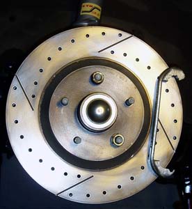
Here are two pictures of the pathetic factory 10.5 inch factory brakes.
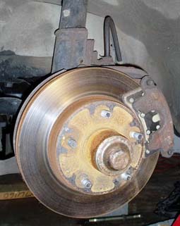
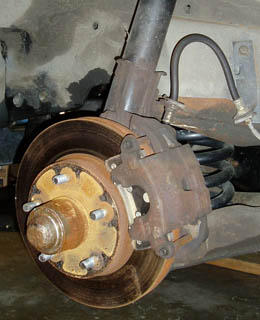
I will not go too in-depth on how to remove the factory setup since this should be pretty trivial for the knowledge and experience level of the people doing brake upgrades.
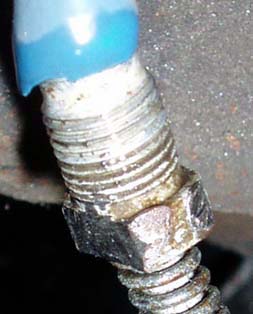
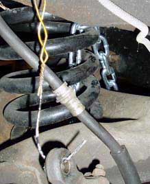
1) Disconnect the factory brake hose from the hard line on the car. Make sure to use a 12mm pipe wrench so not to strip the fitting. If you do ending up stripping the fitting like I did you can still get the line off by using a Dremel tool and grinding down the fitting into a rectangle which you can then use an adjustable wrench to loosen. This can be seen in the picture below. The blue hose is used to cap off the line to prevent dirt from getting into the line and to prevent leaking the master cylinder dry.
2) Remove the factory caliper: This is done by removing two 3/8 inch alien head bolts.
3) Remove the sway bar end-links from the a-arm.
– Method used if rebuilding suspension at same time as brake swap:
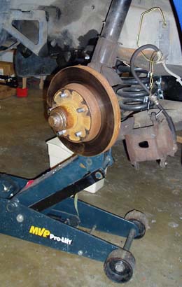
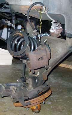
4) I decided to take off the strut and spindle as one unit since all these components where to be replaced in the upgrade. First place a floor jack under the ball joint of the a-arm. Raise the jack until tension is taken off the bolt at the top of the strut, holding it on to the strut tower. Now the important step for safety, wrap a chain or thick rope around the spring and a-arm as seen in the picture below. This prevents the spring from flying out when tension is released when the jack is lowered. Now remove the nut at the top of the strut preventing the stuck from lowering.
WARNING: If care is not taken to fasten the spring to the A-Arm this could be very dangerous! Make sure you fasten the spring to the A-arm securely.
5) Now slowly and carefully lower the jack. As you can see the spring is securely fastened to the a-arm as discussed above.
6) Remove the two bolts holding the a-arm to the cross member and tie-rod and your factory brake and suspension setup is out.
– Method used if NOT rebuilding suspension at same time as brake swap:
4) First place a floor jack under the ball joint of the a-arm. Raise the floor jack until there is almost no pressure on the a-arm, you do not want to compress the strut. Just for safety wrap a chain or thick rope around the spring and a-arm as seen in the picture above. You will not be lowing the a-arm to the ground but just encase the jack fails or you lower the a-arm to low you do not want the spring popping out.
5) Remove the Rotor: Take a small flat head screw driver and wedge it in-between where the bearing dust cap meats the rotor and pry off the dust cap. Remove the cotter pin, now use a socket or wrench and remove the spindle bolt. Now the factory rotor can be removed by pulling it off the spindle.
6) Remove the Strut Bolts: Now that the rotor is removed the strut bolts can be accessed, you may have to removed factory rotor dust shield depending on what tools you have. You need to remove the two strut bolts which can be a hard task, these bolts are tightened extremely tight and require a large breaker bar or air tools to remove.
7) Remove the Spindle: First remove the cotter pin from the ball joint stud on the spindle. Now remove the nut on the ball joint stud. Separating the ball joint stud from the spindle can be tricky to do without damaging the ball joint or ball joint dust boot if using a pickle fork tool. To get around this problem you can use a pitman arm or a tie rod puller.
Install new brake setup:
I will not discuss how to go about rebuilding the whole front suspension in this article since it dedicated to a brake upgrade discussion. If you are rebuilding the front suspension you will be replacing the ball joints, control arm bushings, struts, springs, tie rods, center link, idler arm, etc. I may write a how-to article on this at a later time.
– Start here if rebuilding suspension at same time as brake swap:
1) Install A-Arm: Lubricate the a-arm bushings with grease and insert a-arm into the cross member. If you are using polyurethane bushings make sure to use silicon grease because regular petroleum based grease will eat away at the bushings. Install both bolts into a-arm with the head of the bolt facing the front of the car and the threads of the bolt facing the rear of the car. Tighten the two nuts on the a-arm bolts to 61 ft. lbs.
2) Install Strut: Put the dust shield on strut shaft. Insert strut into upper strut mount and tighten nut on the strut shaft to 44 ft. lbs. To keep the strut shaft from rotating you will have to tighten the nut with open ended wrench while holding the strut shaft with another wrench.
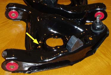
3) Install Spring: There are two methods to do this. The first is an inbound spring compressor, the second is to place the spring in the a-arm spring pocket and use a jack to compress the spring. Since the inbound spring compressor method is pretty straight forward I will discuss the second method. IMPORTANT: If you are a using a jack to compress the spring it is very important to securely fasten the spring to the a-arm with a chain or rope to prevent the spring from popping out during compression. Tape the spring insulator to the top of the spring for ease of installation, this helps keep it in place while installing the spring. Align the bottom coil of the spring between the two drain holes in the a-arm as seen with the yellow arrow in the picture below. Make sure the top of the spring is seat properly in the crossmember. Now place a jack under the front of the a-arm and slowly raise the jack until the a-arm is about parallel with the ground.
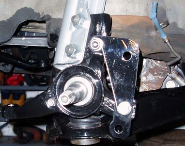
4) Install spindle: Place the bottom of the spindle onto the ball joint and tighten the ball joint nut to 80 ft. lbs. Tighten nut 1/6 of a turn more maximum to align cotter pin hole with nut. Now install a cotter pin. Align the strut with the top two holes in the spindle, you may need to raise or lower the jack a little. Insert the bolts in accordance to the diagram below, make sure you put the washer in the correct location and the bolt in the same direction. Tighten the nuts to 125 ft. lbs. then tighten the nuts another 120 degrees, the final torque must exceed 148 ft. lbs.
Factory Shop Manual Diagram:
Spindle on car:
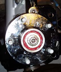
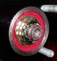
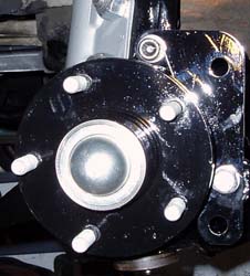
5) Install hub: The hub should already have the rear bearing and seal installed prior to this step. The rear bearing should also be packed with grease. Install the hub onto the spindle shaft, then install a newly packed front bearing into the hub. Install the washer and the spindle shaft nut. The nut should be tighten to 12 ft. lb. and no tighter. Over tightening or under tightening the bearing will result in premature bearing failure. Now install a cotter pin to insure nut doesn’t loosen. I highly recommend using the late style spindle shaft nut which uses a cap to keep it in place as seen below. This cap has many more positions then the old style spindle nuts which have the cotter pin groves cut into the nut. Finally install the bearing dust cap. The best way to do this is place the cap on the hub then use a very large socket or a piece of small exhaust tube that contacts the edges of the dust cap. Hammer the socket / exhaust tube to secure the dust cap. Do not hammer the center of the dust cap to install it.
Picture of hub installed on spindle:
Close up of late style spindle nut and retainer:
After hub is fully installed with dust cap:
6) Install Rotor: Install the rotor onto the hub, use at-least two open ended lug nuts tighten the rotor down. This is importing for the next step where the caliper carrier may need to be shimmed.
7) Install Caliper Carrier: The bolts I used to hold the caliper carrier to the spindle bracket for my setup are __ mm X __ mm X _ mm bolts and 14 mm washers for the back side of the bolt. I also drilled these bolts for safety wiring which is an import added step for safety. If a 3/8 inch bracket is used on your C4-HD setup you will need 1/8 inch thick washers to sandwich between the caliper carrier and spindle bracket. First place the caliper carrier over the rotor and tighten the two caliper carrier bolts firmly with the shimming washers in place. Now measure the distance from the caliper carrier to rotor on the four corners of the caliper carriers using a feeler gauge. The four corners are front of rotor top and bottom and rear of rotor top and bottom. I used very thin washers as shims, sandwiched between the caliper carrier and the spindle bracket to maintain a tolerance less then 0.015 inches between the front measurement and rear measurement. After you install a shimming washer re-tighten the caliper carrier bolts and recheck the tolerance. Shimming the caliper carrier is important for proper pad wear and pad life. After the caliper carrier is properly shimmed tighten to two caliper carrier bolts to 137 ft. lbs. Now safety wire them for piece of mind and safety.
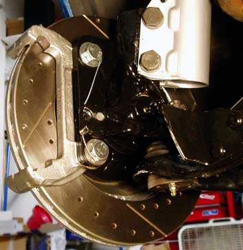
Rotor and caliper carrier installed:
Rotor and caliper carrier installed and safety wired (rear view):
8) Install Brake Pads into Caliper: Place the pad into the caliper, use channel locks to install pad firmly into caliper bores as seen in the picture below. I recommend using a rag in-between the channel locks and pad so not to damage the pad surface.
9) Install Caliper: Tilt caliper in against caliper carrier starting with side opposite to caliper retaining pin. Once caliper is in caliper carrier install the caliper retainer pin from the rear so the c-clip will be on the front of the caliper. Now install c-clip on the retainer pin.
10) Install Brake Hose: Install brake hose with new copper washers and tighten banjo bolt to 30 ft. lbs.
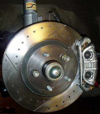
Picture of complete front C4-HD brake setup:
| <– Previous Page (7/9): Spindle Modification | Next Page (9/9): Links –> |
Page created: January 2006
Page content last updated: February 2006
Hi my name is Ryan and I’m trying to do a brake upgrade on my 1984 camaro. I’m confused a little and I’m hoping you can help me out. I am ordering c6 rotors and c6 calipers. What I’m trying to figure out is will my factory brake lines work? Of course I’ll buy new ones but what I’m wondering is will they bolt directly up? Or will the factory c6 brake lines bolt up to the factory hard lines on the car. Please help me with this so I make sure I order the correct parts. Thanks for your time.
Ryan
Do you still need adapters to run corvette rims after this upgrade