Programming 101
Bruce Plecan
The Programming 101 project analyzes GM OEM fuel and ignition management issues.
Several EFI DIY’erst are focused the GM 1227747 ECM, a TBI system, used in 4/6/8 cylinder GM trucks and Vans from 87-91. We hope to develop and understanding of the location (addresses) and function of all the tables in the EPROM. Once this is accomplished the knowledge can be applied to other GM ECM’s.
Changing the calibrations of your ECM may violate the laws in your area. If you attempt recalibrations, serious engine damage may result. These matters should be done under adult supervision. Again this is in general for GM ECM’s, and most specifically the 1227747.
The 1227747 ECM uses a socketed PROM that contains all of the calibration and a part of there algorithm; $0000 to $0616 Relative, (actual address is $D000 – $D616),. The remainder of the algorithm is stored in a special device that has a masked ROM, $0616 – $1FFF relative, $D616 – $EFFF
| CPU ADDRESS | RELATIVE ADDRESS | EEPROM | ROM |
| $DOOO – $D616 | $0000 – $0616 | YES | NO |
| $D617 -$EFFF | $0617 – $1FFF | NO | YES |
| Note: Motorola code uses the “$” to indicate hex values | |||
The 1227747 ECM uses a GM unique derivative of the Motorola 6803 not available commercially.
Editors note:
Bruce used the version 1.3 of WinTuner to show the construction of the calibrations tables and functions.
Tables and their locations in the EPROM:
Click on the address to jump to the description
| Address Range | Purpose |
| $0000-0001 | Checksum |
| $0002-$0003 | Scan ID |
| $0004 | EPROM Template ID |
| $0032-0106 | Main Spark table, 3d |
| $015E-0165 | WOT Spark adder |
| $017F-0187 | Knock sensor retard at WOT |
| $0188-018C | Knock sensor retard non WOT |
| $030E-0312 | MAP Power Enrichment |
| $0314-031D | TPS Power Enrichment |
| $037F-03C6 | Main Fuel table, 3d |
| $03C7-03D7 | Main fuel table Adder |
| $044A-0458 | Crank Air Fuel Ratio Vs Coolant |
| $0459-0468 | Air Fuel Ratio Vs Coolant |
| $047D-0485 | Percent of TPS to enable PE |
| $050D-050F | Error Code Masks |
| $05F5-0605 | Air Fuel Ratio Vs Coolant |
| $060E-0616 | Idle Speed Temperature Corrections |
Units and Scalars
All these tables are used in a similar fashion. You index
into the table using one or two values (MAP, RPM, temp, etc.), and retrieve the value
stored there.
Table indices are fixed by the algorithm in the ROM, but what about the value stored in tables? How is the value there converted to a real world number representing spark angle, volumetric efficiency, etc? See the table below. In this table, “N” represents the value retrieved from the table.
| Unit Type | Calculation | Units |
| Temperature, Coolant | N x (191/255)-40 | degrees C |
| Speed | N x 1 | 0-255 MPH |
| RPM | N x 25 | RPM |
| RPM, low range | N x 12.5 | RPM |
| WOT AFR | N x (100/256) | AFR |
| PE (power enrich) | N x 10 | |
| VE (volumetric efficiency) | N x (256/100) | 0-100% |
| Knock retard | N x (45/256) | 0-45 degrees |
| Knock attack Rate | N x 0.0225 | milliseconds |
| Knock recovery Rate | N x (500/256) | milliseconds |
| Spark Advance | N x (90/256) | 0-90 degrees |
| Spark Retard | N x (45/90) | 0-45 degrees |
Example:
If you looked in the knock retard table, you might find the value $44 (68 decimal). What’s is this in real world units? take the table value, multiply by 45 and divide by 256, which gives 11.9. That’s almost 12 degrees of retard when knock is detected.
Here is a table for converting between pressure units. kPa and PSI are in absolute pressure, in-hg is in gauge pressure as you would see it on a vacuum gauge.
| 0 – 1 Bar Pressure Conversion | 1 – 2 Bar Pressure Conversion | ||||||
| MAP | MAP | MAP | (Vacuum) | MAP | MAP | MAP | |
| Kpa | PSIA | in hg | in hg | Kpa | PSIA | in hg | |
| 5 | 0.7 | 1.5 | 28.5 | 105 | 15.2 | 31.0 | |
| 10 | 1.5 | 3.0 | 27.0 | 110 | 16.0 | 32.5 | |
| 15 | 2.2 | 4.4 | 25.6 | 115 | 16.7 | 34.0 | |
| 20 | 2.9 | 5.9 | 24.1 | 120 | 17.4 | 35.4 | |
| 25 | 3.6 | 7.4 | 22.6 | 125 | 18.1 | 36.9 | |
| 30 | 4.4 | 8.9 | 21.1 | 130 | 18.9 | 38.4 | |
| 35 | 5.1 | 10.3 | 19.7 | 135 | 19.6 | 39.9 | |
| 40 | 5.8 | 11.8 | 18.2 | 140 | 20.3 | 41.3 | |
| 45 | 6.5 | 13.3 | 16.7 | 145 | 21.0 | 42.8 | |
| 50 | 7.3 | 14.8 | 15.2 | 150 | 21.8 | 44.3 | |
| 55 | 8.0 | 16.2 | 13.8 | 155 | 22.5 | 45.8 | |
| 60 | 8.7 | 17.7 | 12.3 | 160 | 23.2 | 47.2 | |
| 65 | 9.4 | 19.2 | 10.8 | 165 | 23.9 | 48.7 | |
| 70 | 10.2 | 20.7 | 9.3 | 170 | 24.7 | 50.2 | |
| 75 | 10.9 | 22.1 | 7.9 | 175 | 25.4 | 51.7 | |
| 80 | 11.6 | 23.6 | 6.4 | 180 | 26.1 | 53.2 | |
| 85 | 12.3 | 25.1 | 4.9 | 185 | 26.8 | 54.6 | |
| 90 | 13.1 | 26.6 | 3.4 | 190 | 27.6 | 56.1 | |
| 95 | 13.8 | 28.1 | 1.9 | 195 | 28.3 | 57.6 | |
| 100 | 14.5 | 29.5 | 0.5 | 200 | 29.0 | 59.1 | |
Checksum, $0000 – $0001
To calculate the checksum:
- Add all bytes in the EPROM, starting immediately after the Checksum word itself.
- Truncate the result to 16 bits (4 hex digits).
- The result is the checksum.
Example:
- Add all bytes starting at relative address $0002 and continuing to the end of the EPROM, ($0616).
- The result was found to be 72,182 decimal, or $123456.
- Truncating the result to 4 hex digits results in $3456, the new checksum.
Scan ID Word, $0002 – $0003
The Scan ID word is the last four digits of the software part number.
This number can be looked up to verify which software in the EPROM.
Note: This function is found at the same address for most early ECM’s using 32K EPROM’s.
ID Byte, $0004
Address $0004 contains the calibration ID byte. The value generally found in the 1227747 ECM is $42, this is the production code.
In some ECM’s several different software variations (different ID byte), may be in use although the ECM service number is the same.
If the value $AA is stored here then the ECM does not perform a checksum test, This is considered the engineering code.
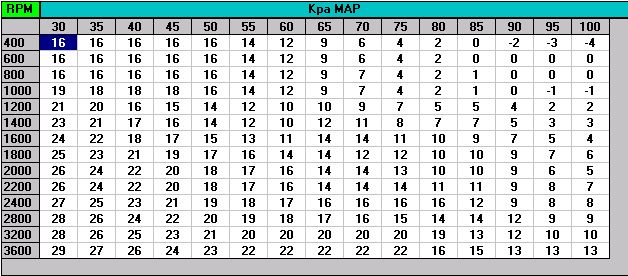
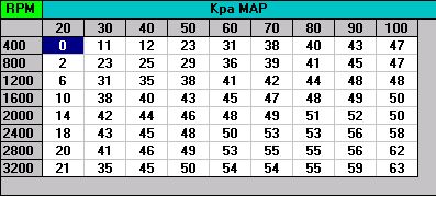
Spark Table, $0032 to $0106
The Main Spark Table is a 3D table is organized as a 14 row by 15 column tables as shown below
There is a three byte header that define the minimum RPM value, minimum Map Value and the number of rows in each column.
The total spark applied to the engine is the summation of several values, this table is the base value.
Maximum Spark Retard Vs. RPM, $017F – $0187
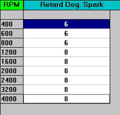
These values limit the amount of spark that can be subtracted from the total spark in use at a particular RPM. I like to zero these values while I’m tuning, then restore them when I’m done.
Maximum Knock Retard Vs. MAP, $0188 to $018C
WOT a 2D table using MAP as the look up value
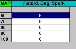
- The value to store in the table is the retard in degrees, multiplied by 5.688 (256/45)
- To use12 degrees of knock retard do: 12 x (256/45) = 68, or $44.
Same as the RPM table above only this table is MAP selected.
Accelerator pump enrichment
TBI systems needs to emulate the accelerator pump found on carbureted engines. The accelerator pump on a Carburetor injects a big squirt of fuel into the manifold when the throttle is opened quickly. There are three reasons for this extra fuel in that case of a carbureted engine:
- The sudden opening of the throttle lets in more air, which the ventures can’t immediately respond to.
- The sudden opening of the throttle increases the absolute pressure in the manifold, which can cause some of the vaporized gas to condense into a liquid on the manifold walls.
- At WOT you want more fuel anyway to make the most power.
The TBI system has a slightly different problem, since it can react to rapid opening and it has a TPS sensor to tell the CPU about that fact, and we don’t need all that mush fuel at WOT, because we can control fuel much better than a Carburetor.
The TBI suffers from the long delay from the time fuel is called for by the CPU and the time it combusts and ultimately become an o2 signal in the exhaust at the o2 sensor. This is called “transport time”.
The type $42 code running in the 1227747 ECM uses the following two tables to provide acceleration enrichment.
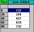
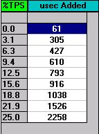
Acceleration Enrichment Vs. MAP, $030D – $0312
(Pump Shot)
This table uses change in MAP from one cycle of the ECM to the next as Differential MAP.
Note:
Address $030D is an eight bit value defining a 5 line table.
Acceleration Enrichment Vs. TPS, $0313 – $03
(Pump Shot)
Note:
Address $0313 is an eight bit value defining a maximum of 25% TPS that may be used for look up.
Power Enrichment Spark Correction, $015D to $0165
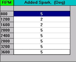
When modifying remember that it’s better to start with too much fuel and too little spark, and slowly sneak up on better values.
Note:
$015D Is a one byte value limiting the maximum RPM to 3600 for this table.
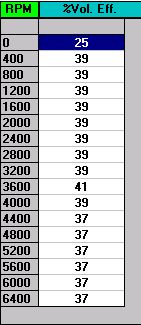
Main Fuel tables, $037C to $03C6 and
This is the main 3D fuel delivery table and its companion 2D table The value in the table is volumetric efficiency, which is used ultimately in the fuel calculation to determine the injector pulse width along with RPM, and coolant temperature, This is why this is a speed/density system.
Fuel is the easiest parameter to get right, record the Block Learn Value when the Integrator if neutral (Near 128). Divide the BLM value by 128 and you have the current error from 14.7:1 AFR.
Example:
At 2000 RPM and 50 Kpa:
BLM = 140
140/128 = 1.09, a 9% error in the lean side
What this indicates is that the BLM is multiplying the calculated value of fuel by 1.09 to achieve 14.7:1 AFR (The Stocheometric point)
To improve this situation got to 200 RPM and 50 KPA map on the fuel table and multiply the value of VE by 1.09, (46 x 50.14), we round to 50 and move on.
Make sure the total of the two table is less that 100.
Sample table from a stock 5.7l truck.
Note:
The table starts with a three byte header that defines minimum MAP, minimum RPM and the number of row /column
VE Adder Table, $03C7 – $03D7
Note:
The VE value used is the result of both table summed. Summed values exceeding 100% will be limited to 100%
Cranking AFR Vs Coolant, $0449 – $0459
These values are used in open loop while cranking.
Percent of TPS to enable Power Enrichment, $047D – $0485
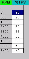
This table tells the ECM when to enter PE mode, based on the TPS.
IAC STEPS Vs. Coolant, $05F5 – $0605
Controls idle speed based on engine temperature until the Idle speed PID loop can get control of idle RPM. see Idle RPM Vs. Coolant
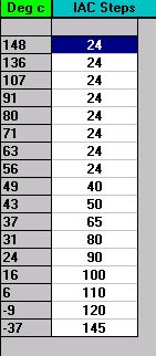
After the PID loop has taken control of Idle RPM, the count will be around 10 -20
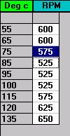
Idle RPM Vs. Coolant
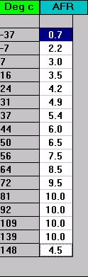
Air Fuel Ratio Vs Coolant, $0459 to $0468
These values are used during open loop operation
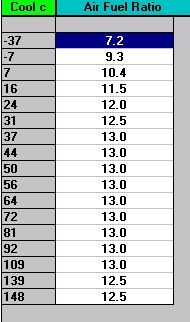
This table details corrections to the A/F ratio, based on engine temperature. It includes startup enrichment (choke).
Error Code Masks 1 through 3.
These three eight bit values specifies the diagnostic codes that are enabled.
Disabling a code does not necessarily turn off the corresponding test. It does prevent a failure code from being stored and prevents the check engine light from coming on.
Each address has an 8 bit value stored, and each bit controls a particular diagnostic code.
Example: $050D has the value $FC. (1111 1100 in binary). The two zeros are in the LSB (least significant bit) (b0 & b1), that means codes 24 and 23 are disabled.
Mask for Error Flag 1
$050D, 1111 1100b
bit0 code 24, VSS
bit1 code 23, MAT Sensor low temp, (Not Used)
bit2 code 22, TPS low
bit3 code 21, TPS hi
bit4 code 15, Coolant sensor low
bit5 code 14, Coolant Sensor Hi
bit6 code 13, o2 sensor
bit7 code 12, No ref’s, (engine not running ?)
Mask for Error Flag 2
LD50E, 0011 1001
1 b0 code 42, EST Mon error
0 b1 code 41, NO DRP , (Not Used)
0 b2 code 35, IAC ERROR, (Not Used)
1 b3 code 34, MAP Sensor low
1 b4 code 33, MAP Sensor hi
1 b5 code 32, EGR failure
0 b6 code 31, MAP LOW, (Not Used)
0 b7 code 25, MAT Sensor high temp, (Not Used)
Mask for Error Flag 3
LD05F, 1111 1001
1 bit 0 code 55, ADU Error
0 bit 1 code 54, Fuel pump relay malfunction
0 bit 2 code 53, VATS, (Not Used)
1 bit 3 code 52, Cal-pack missing
1 bit 4 code 51, EPROM error
1 bit 5 code 45, o2 Rich
1 bit 6 code 44, o2 Lean
1 bit 7 code 43, ESC failure