Introduction:
I have created code and an interface that allows an Atmel AVR or Nintendo DS to control a DSLR camera through a FTDI Vinculum USB host controller. The code implements a very basic subset of the Picture Transfer Protocol (PTP) / Picture Transfer Protocol (MTP) protocols which are used on DSLRs and many point and shoot cameras. This interface allows an Atmel AVR or Nintendo DS to control a modern USB camera such as a DSLR. I wanted to do this to create a standalone HDR controller without the need to haul around a laptop. For more background information on why I decided to do this and the CPLD interface I created to allow a Nintendo DS to talk to the FTDI Vinculum please read my previous blog post. I got the Nintendo DS / AVR USB controller working in June and have not changed the code since August so it is long overdue for me to post the code and schematic.
The code was written and developed on an Atmel AVR (non-Arduino) and ported over to the DS. It is much easier to develop code on an AVR then on the DS which you have to constantly swap SD cards on every recompile. I wrote the code to be as platform independent as I could so it can be moved to whichever device needed. I do not think it would be too hard to add to the Open Camera Control Project (OCC) (talked about in last blog post) code, you will need to call a few functions to init the Vinculum and to take picture, change exposure time, etc.
The Nintendo DS Hardware:
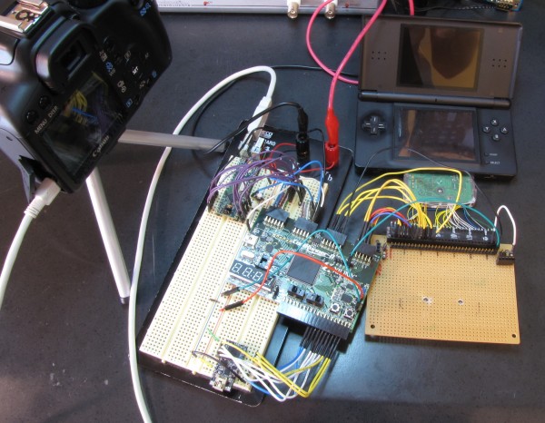
In my bread-boarded prototype I am using a FTDI Vinculum USB host controller for the USB interface. A Xilinx CoolRunner-II CPLD to convert the Nintendo DS SLOT-2/GBA DMA interface to the FTDI PFIFO.
 Nintendo DS to FTDI Vinculum USB host controller interface prototype
In the picture above there are only two main components used on the development boards; the Xilinx CPLD and the Vinculum USB host controller, everything else is for development and debugging. The eval board on the bottom right of the bread board is a FTDI 2232H eval board. I tested\debugged the CPLD interface with a FTDI 2232H instead of a FTDI vinculum which uses the same parallel FIFO interface. Using the FTDI 2232H just lets the DS communicate with a computer instead of the USB host controller for easy debugging.
Annotated Video of Nintnedo DS to FTIDI Vinculum USB host controller in operation
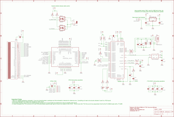
 Schematic of Nintnedo DS SLOT-2/GBA to FTDI Vinculum USB host controller interface
You can download the PDF version of this schematic here: NDS_to_FTDI_Vinculum_USB_Host_Controller.pdf
In the schematic above I use a Xilinx XC9572XL CPLD instead of the CoolRunner-II CPLD I used in my prototype. I did this to lower the cost and for simplicity. The CoolRunner-II requires a 1.8V core voltage which can easily be accomplished with a linear LDO 1.8v regulator but I did not see a need for the CoolRunner-II and the extra cost of the device. I wired the camera shutter release so that the FTDI Vinculum or the CPLD could trigger the camera. The FTDI_C_FOCUS and FTDI_C_SHUTTER will need to be ORed in the CPLD with the internal trigger lines. Moving on to the camera USB connection you can see that I added the ability for the user to supply power for the USB 5V but it is important to note this should not be used and is not needed for cameras. USB power is only needed by devices that are powered off the USB bus such as a flash drive.
The Atmle AVR Hardware:
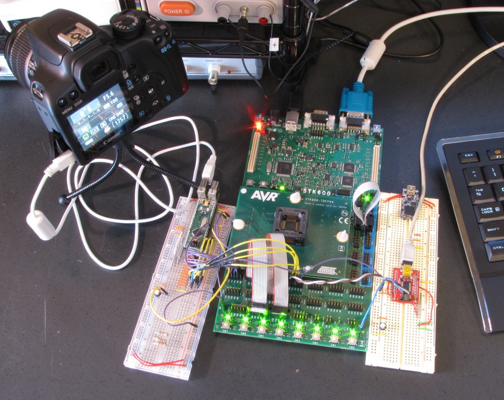
I have been using a Atmel ARV to develop the code for the HDR controller. I chose a ATmega644 uC (what I had laying around) on a Atmel STK600 development board.
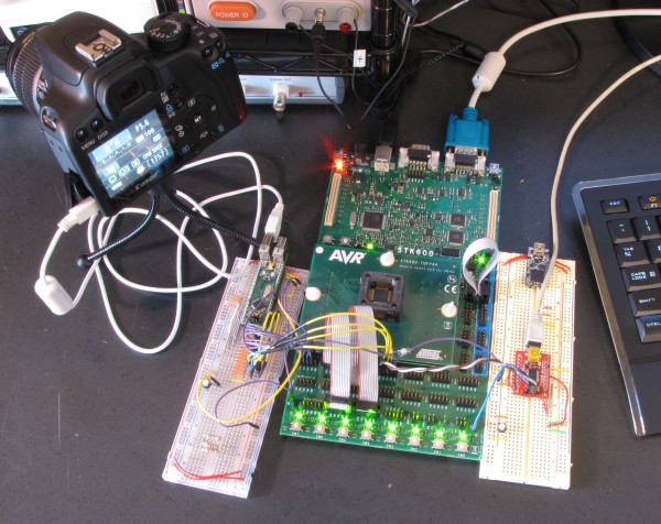
 Atmel STK600 Development board connected to a FTDI VDIP2 vinculum USB host controller development board
In the picture above starting from left to right is a Canon Rebel Xs (1000D) DSLR, breadboard with a FTDI VDIP2, Atmel STK600, and a breadboard with a FT232RL (USB to UART) used for terminal debugging and error output of the code.
Annotated Video of Atmel AVR to FTIDI Vinculum USB host controller in operation
In the video above the code commands the camera to do a eight second exposure to demonstrate how the code actively pings the camera waiting for the shot to finish. Once the shot is completed and the camera is ready the code fires off a seven shot HDR, between each shot the code waits for the shot to finish before commanding the camera to change the shutter time and fire another shot.
The Code:
As discussed above the code is written to be as platform independent as I could. The code is by no means complete and as it stands is more of a proof of concept. The basic framework needed for PTP/MTP transactions is implemented, PTP/MTP sessions can be started, events can be read, and the camera can be commanded to change settings and take pictures.
AVR/NDS to FTDI Vinculum USB host controller PTP/MTP implementation: USBCameraControl_v0.01.zip
The Next Step:
The FTDI Vinculum-II USB host controller recently was released, this new IC is a USB host controller with a programmable 16-bit uC on-board and free IDE. It is the logical next step and the addition of a user programmable on-board uC expands the possibilities quite a bit, it would allow for a complete one chip stand along solution without the need for a Nintendo DS or AVR.


thanks for the great article! It has pushed me in the direction of the vinculum-2 and I’m hoping to replicate the work you’ve done by developing a firmware allowing (easy) control of a canon dslr (50D & 60D – hoping to work out the commands required to record video; any ideas?) via SPI. I’ll be sure to post details of any progress I make…
Hi Tom, I do not think the Vinculum II has the throughput needed to handle video. The Vinculum I is extremely slow and can only be used for basic commands. The Vinculum II is faster but all the data is still being passed through a uC.
Sorry I wasn’t clear; I just want to issue the commands to start recording video (planning to synchronise up to 4 60Ds), and again to stop it, saving all the data to the memory card!
I’m rather interested in this project as I have been looking for a way to create a general purpose USB host for the NDS. I would like to see the ability to provide an external 5V. While I can not be much help with the hardware, I can do quiet a bit in software. If you are interested in producing a batch order, I would like to be on that list.
bread board… I remember during my electronics laboratory in college :)
Hey Luke,
This is a really interesting project and quality work you’ve put together. Great build. Do you have an email I can catch you on? I have a few questions.
Thanks
Ryan
Hi Luke,
unfortunately I was not able to get USBCameraControl_v0.01 compiled for my NDS I’m using MS C++ 2008 Express, I already tried to remove the AVR stuff but still not able to get it to run…
Any help or a newer version available?
Many thanks in advance…
Joerg
Hi Joerg,
Sorry for the really delayed response. I only used this code on the NDS very early on. It became far too big of a hassle to have to swap SD cards and reboot on every recompile. That is why I moved the code over to AVR. It very well could no longer work on the NDS but the core functions and addresses are there that are needed. I lost interest in the project once someone finally made a app to do this on a smart phone, “DSLR Controller” for android.
Hey,
I’m working on a project related to this, and I was curious how you found out the operation codes for the Canon DSLR? I have a T2i, so I assume the ones you used will be similar, but there are some more PTP/MTP operations I want to implement. If you have any advice, it’d be much appreciated.
Cheers,
John
Replying to myself in case anyone else tries to conquer similar things… here is a website that list operation codes and event codes for a whole lot of cameras:
http://www.circuitsathome.com/ptpusb-control-camera-data#EOS550D
Cheers,
John
Hi John, I got some of canon’s command set from the gphoto (libgphoto2) open source linux program code and a great deal from packet sniffing the USB protocol as I sent commands to my camera from my computer.
Luke
Hey Luke,
I was curious about this line in FTDI_IO.c:
(lastByte == 0x3A) && (inByte == 0x0D)
I’m trying to get this to work with a VDIP1 and Rebel (550D). It seems like those first FTDI_RX_Byte()’s are always returning 0xFB, so it gets hung in the FTDI_init() function. Where did you come across the 0x3A and 0x0D specification? (FTDI’s documentation is… non-existent basically)
Err it’s actually always returning 0xFF
Nevermind! Forgot to change the FTDI_CTRL port direction since I’m using PortA instead of D.
Cheers,
John
(Sorry for the spam!)
Hi, I just saw your project which is amnazig and it is so nice that you could share your design. I am working on a similar project about waveform generator. At first I am going to use MAX038 which is not produced anymore. And your design helps a lot. I want to know what is the maximum frequency it could get. In my project, this generator works as a modulator. So I really care about the highest frequency it could get. Thank you again!